
STRUCTURAL SUBSTANTIATION REPORT

Before going into production, Quickrax needed to validate the structural integrity of the Avionics Tray Mount Rail system. Using an instrument panel simulation test bed with the capability of G-load testing a sample avionics suite to the point of ultimate failure provided valid and calibrated results that can be confidently applied to real-world installations.
The following report details a Quickrax QP1020 Rail Set static load test in accordance with 14 CFR § 27.307 - Proof of structure (rotorcraft), 14 CFR § 23.2230 - Limit and ultimate loads (fixed-wing aircraft), and AC43.13-2B § 1.103-108. This report is intended to be used as evidence and support for FAA 337 Field Approval of a Quickrax QP1020 / QP1050 / QP1120 Tray Mount Rail installation in certificated aircraft.
Setup
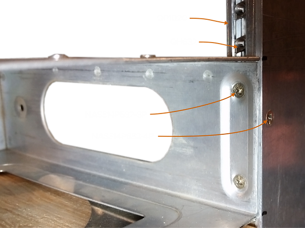
A welded steel test stand was constructed of 1.5" square tubing and an instrument panel constructed from a 6061T6 14"W x 16"H x .125"T aluminum sheet with a centered 6.25"W x 12"H avionics bay cutout was mounted to the stand. Two QP1020 rails were cut to 12.5" length and both were #6-32 tap/drilled in 6 locations spaced equally in 2.25" increments. The rails were mounted to the panel using NAS514P632-4P screws with the avionics tray mounting faces spaced at 6.30" ID centered on the 6.25"W avionics cutout.
Bendix King Weight
KMA24 Audio 1.7 lb
KX155 NAV/COM 5.1 lb
KR86 ADF 3.3 lb
KT76a Transponder 3.1 lb
TOTAL 13.2 lb
AVG CG 4.45"
Avionics
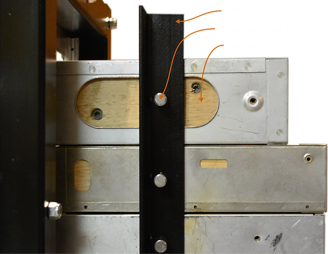
Four Bendix King avionic trays were mounted to the QP1020 rails using NAS514P632-3P screws. Condition of the trays was "heavily used" with enlarged and sometimes elongated mounting holes. This represents a worst-case scenario for installation integrity. The avionics stack was installed inverted to simulate a "down" G-force when testing. Wood Test Blocks cut to each avionic unit's dimensions were installed in each tray to more accurately distribute the reaction forces during the G-load test.
Reaction Force Yoke
A Reaction Force Yoke was constructed using 1.25" steel angle uprights welded to a 1.50" steel square tube base. A 0.50"D hole is centered, drilled, and chamfered on the lower face of the base tube to be the Receiver Cup for the Reaction Force Bearing. The reaction force is directed into each avionic unit Test Block at the average CG arm of the entire test avionics suite. For this test, average CG moment was computed to be 4.45" from the panel face. A 0.375"d hole was drilled longitudinally through each Test Block at this distance and coupled to the Reaction Force Yoke using 8.0"L x 0.375"D steel Reaction Force Rods.

Ultimate G-Load Test
On 12/11/2018 a static load test was conducted to validate a prototype QP1020 Tray Mount Rail Set installation on a static load test fixture. Test goals were to demonstrate the ability of the Quickrax Tray Mount System to meet or exceed the down force Limit Load Factors for part 23 and part 27 certificated aircraft, and to determine the Ultimate Failure Load for the given test installation. Load force readings were taken using a M2000-3-10CS Aircraft Weighing Kit within Current Calibration.
AC43.13-2B § 1.103 specifies five Static Load Force Directions with corresponding Limit Load Factors for each aircraft category: Sideward, Upward, Forward, Downward, and Rearward. Downward Force was the direction chosen for this test because it represents the highest G-force with the greatest twisting moment for a cantilevered (no back-strap) avionics installation. The results of this specific test showed that the Safety Factor was so high that further testing of other force directions was considered to be moot.
Target Ultimate Load Forces are:
Load Test Video Proof
Results
The load force was slowly applied using a hydraulic jack as the force generator. The avionics suite and QP1020 test rails quickly surpassed the Part 23 Normal-Utility Downward Ultimate Load with 0.1° Tray Deflection. Next, Part 23 Acrobatic Ultimate Load passed with 0.2° Tray Deflection, and Part 27 Rotorcraft Ultimate Load passed with 0.9° Tray Deflection. There was no damage or permanent deformation or dislocation of any part or component of the avionics installation at these load levels.
The determination was made to continue adding load force until obvious deformation or failure of the avionics trays was observed. The results were beyond satisfactory. The force was increased to a maximum of 680 lb. with increasingly applied force being exerted over a time period of 3½ minutes. The result at the maximum applied force was a slowly increasing tray deflection that maxed out at 3.0°. At this point it became apparent that the trays were entering a plastic stage of deformation and the test was terminated.
50+G Post-test Analysis
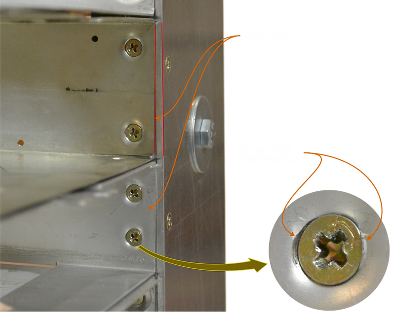
After the test, components were disassembled and inspected for permanent deformation and other stress factors. No dimensional changes in the QP1020 rails or the QH632 nut assemblies were noted. The trays were permanently deflected 0.7° as a result of the extreme 50+g Ultimate Failure Test, but no buckling or structural damage to the trays was noted except for the already compromised mounting holes being slightly further deformed. It is believed that new trays would not have exhibited mounting hole deformation at this level of G-Force, thereby indicating an even higher Ultimate Failure for new installations than was demonstrated by the test.

Conclusion
The Quickrax Tray Mount System is Stronger than standard OEM avionics installations that usually incorporate back-strapping to achieve acceptable rigidity.
Installing and moving trays is Faster with mounting hardware that easily moves to the correct fastener location and no need for time consuming back-strapping.
With optimized extrusions and purpose-built hardware, the entire installation is Lighter than any other method available.
The Quickrax Tray Mount System in a full cantilever avionics installation is proven to withstand down forces in excess of 50g while maintaining avionics tray integrity without back-strapping.